2D games just wouldn’t be the same without sprites. Before you start thinking soda or fairies, sprites
are 2D graphical representations of characters or objects within a
game. Every tree, treasure chest, or dungeon creature you encounter is presented
on-screen using a sprite. Sprites are one of the most widely used and
easily understood aspects of 2D game programming. Figure 1 shows an example of a sprite created from a colored rectangle.

Sprites come in all
different sizes, but tend to come in only one shape, rectangular.
Because of their shape, sprites need only a width and height to define
their area and are more easily controlled from a programmer’s
perspective. Since your game is taking place in a 2D area consisting of
only width and height, it only takes two variables to describe the
sprite’s location. These two variables are commonly referred to as X and
Y. The X variable controls the horizontal position with Y controlling
the vertical.
Moving a character
sprite along a straight line from one side of the screen to the other is
simple. The sprite’s location need only change horizontally, without
any concern for depth. Because of the lack of actual depth in
sprite-based games, depth is normally faked by a technique called Z
ordering.
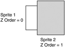
Z Ordering
Z ordering
is the process in which objects are sorted before being drawn. Each
sprite you create can be given a different Z-order value designating the
depth at which it should be drawn. Sprites with a lower Z-order value
are drawn behind those sprites with a higher value, giving the illusion
of depth. Figure 2 shows how Z ordering works.
Sprite Image
The
most important aspect of a sprite is its image. Each sprite needs an
image to be associated with it both from a gameplay perspective and a
technical one. The image is what the sprite uses to convey its purpose
to the player. For instance, your main character sprite in an RPG game
may be the image of a knight or even a spaceship in a space battle. You
can choose any image you’d like, but your sprite can’t be displayed
without an image.
Earlier you learned how to load a texture from the disk; now you’ll learn how textures can be used with sprites.
Shader Resource Views
Before a texture can be
attached to a sprite, it needs to be configured into a format the sprite
can use. The way resources are accessed in Direct3D differs based on
how the resource is going to be used. Resources, such as textures, are
commonly stored linearly in a buffer within memory. While this is an
easy way to load the texture, it isn’t always in the format that is most
efficient for the video hardware. Direct3D solves this problem by using
resource views.
A resource view allows
data to be accessed differently based on part of the Direct3D pipeline
using it. When creating a sprite, the D3DX10_SPRITE structure expects the texturetobeaccessedthroughan ID3D10ShaderResourceView object, which helps the shader know how to use a particular resource.
The ID3D10ShaderResourceView is created using the CreateShaderResourceView function.
The CreateShaderResourceView function takes three parameters.
The first parameter is a pointer to the texture resource from which to create the view. The second parameter is a pointer to a D3D10_SHADER_RESOURCE_VIEW_DESC structure. This structure is used to define the type of resource view being created. The final parameter is the newly created ID3D10ShaderResourceView.
Before the shader resource view can be created, you need to create and fill out the D3D10_SHADER_RESOURCE_VIEW_DESC structure.
typedef struct D3D10_SHADER_RESOURCE_VIEW_DESC {
    DXGI_FORMAT Format;
    D3D10_SRV_DIMENSION ViewDimension;
    union {
        D3D10_BUFFER_SRV Buffer;
        D3D10_TEX1D_SRV Texture1D;
        D3D10_TEX1D_ARRAY_SRV Texture1DArray;
        D3D10_TEX2D_SRV Texture2D;
        D3D10_TEX2D_ARRAY_SRV Texture2DArray;
        D3D10_TEX2DMS_SRV Texture2DMS;
        D3D10_TEX2DMS_ARRAY_SRV Texture2DMSArray;
        D3D10_TEX3D_SRV Texture3D;
        D3D10_TEXCUBE_SRV TextureCube;
    };
} D3D10_SHADER_RESOURCE_VIEW_DESC;
Although the size of the D3D10_SHADER_RESOURCE_VIEW_DESC structure may look imposing, there are only a few variables that need to be filled out.
The DXGI_FORMAT is simply the texture format. This information is available in the D3D10_TEXTURE2D_DESC structure by calling the GetDesc function.
The D3D10_SRV_DIMENSION lets the resource view know the type of texture it is representing. This will most commonly be a 2D texture.
The last piece is to fill
out the variables that pertain to the type of texture resource. In the
case of 2D textures, this includes information like the number of mip
levels.
The following code sample shows how to create and complete the D3D10_SHADER_ RESOURCE_VIEW_DESC structure.
// Load the texture for the sprite
ID3D10Texture2D* texture = GetTexture2DFromFile(TEXT("../brick.bmp"));

// Make sure there's a valid texture
if (texture != NULL)
{
    // Get the texture details
    D3D10_TEXTURE2D_DESC desc;
    texture->GetDesc( &desc );

    // Create a shader resource view of the texture
    D3D10_SHADER_RESOURCE_VIEW_DESC SRVDesc;
    // Clear out the shader resource view description structure
    ZeroMemory( &SRVDesc, sizeof(SRVDesc) );

    // Set the texture format
    SRVDesc.Format = desc.Format;
    // Set the type of resource
    SRVDesc.ViewDimension = D3D10_SRV_DIMENSION_TEXTURE2D;
    SRVDesc.Texture2D.MipLevels = desc.MipLevels;
}
Once you have a completed D3D10_SHADER_RESOURCE_VIEW_DESC structure, you can call the CreateShaderResourceView function. The following code shows how to use this function to create a resource view.
ID3D10ShaderResourceView *gSpriteTextureRV = NULL;
pD3DDevice->CreateShaderResourceView(texture, &SRVDesc, &gSpriteTextureRV);
When the call is complete, the gSpriteTextureRV function will contain a valid shader resource view usable to create a sprite.
Creating a Sprite
Now that you have your
image data ready, it’s time to create the sprite. Direct3D has built-in
support for sprites so there won’t be a need to mess with the textures
directly like you did in the first example.
There are a few easy steps you need to follow to create a sprite. First, define each of your sprites using a D3DX10_SPRITE structure. Second, use the ID3DX10Sprite interface to manipulate and draw the sprites. The steps are detailed in the following sections.
The D3DX10_SPRITE Structure
Direct3D has a special object reserved specifically for representing sprites: the D3DX10_SPRITE
structure. This structure contains variables for specifying everything
Direct3D needs to know in order to draw the sprite, including its
position, texture, resource, and color. By filling in this structure,
you’re detailing how and where you want your sprite drawn by Direct3D.
Each sprite your game displays will need one of these structures filled
out with the sprite’s appropriate data.
typedef struct D3DX10_SPRITE {
    D3DXMATRIX matWorld;
    D3DXVECTOR2 TexCoord;
    D3DXVECTOR2 TexSize;
    D3DXCOLOR ColorModulate;
    ID3D10ShaderResourceView * pTexture;
     UINT TextureIndex;
} D3DX10_SPRITE;
The first member of the D3DX10_SPRITE structure is the matWorld variable. This variable contains the transform used to specify where the sprite should be drawn.
The second member is TexCoord;
this is the sprite’s texture coordinate. The texture coordinate
describes the location of the sprite’s top-left corner in its image
data. This value ranges from 0 to 1.
TexSize
details the size of the texture used for the sprite. This value, ranging
from 0 to 1, will tell the sprite just how much of the image data it
uses.
The fourth member is ColorModulate.
Whichever color is specified in this variable will be applied to the
sprite before it’s drawn. If the sprite is being drawn at full
brightness and color, this variable is normally white.
pTexture is a pointer to the shader resource view that represents the texture the sprite will use.
Lastly, TextureIndex
is the index into an array of textures. If the texture being used for
the sprite is not a texture array, this value should be 0.
The following small code sample shows how to create and initialize a sprite using the D3DX10_SPRITE structure.
// Create a new sprite variable
D3DX10_SPRITE testSprite;

// Set the sprite's shader resource view
testSprite.pTexture = gSpriteTextureRV;

// top-left location in U,V coords
testSprite.TexCoord.x = 0;
testSprite.TexCoord.y = 0;

// Determine the texture size in U,V coords
testSprite.TexSize.x = 1.0f;
testSprite.TexSize.y = 1.0f;

// Set the texture index. Single textures will use 0
testSprite.TextureIndex = 0;

// The color to apply to this sprite, full color applies white.
testSprite.ColorModulate = D3DXCOLOR(1.0f, 1.0f, 1.0f, 1.0f);
The preceding code
assumed that the sprite was using the entire contents of the image by
specifying 0 for the texture coordinates and 1.0 for the texture size.
The Direct3D Sprite System
Direct3D includes an interface for managing and drawing the sprites defined in the D3DX10_SPRITE structures. This interface, ID3DX10Sprite, is the main workhorse of sprite drawing. The ID3DX10Sprite
interface expects the application to create one or more sprite
structures for it to manage. It takes the structures, sorts them, and
sends them to the graphics hardware to be drawn.
You can create an ID3DX10Sprite object using the D3DX10CreateSprite function. The D3DX10CreateSprite function takes only three parameters.
The first parameter is a pointer to the D3DX10Device you created when Direct3D was initialized.
Second is the number
of sprites to be rendered at any one time. Specifying 0 for this
parameter will cause Direct3D to default to 4096.
The final parameter is a pointer to an ID3DX10Sprite interface waiting to be initialized.
The following code sample shows how to create and initialize the sprite system.
ID3DX10Sprite   *spriteObject = NULL;

// create the sprite object
HRESULT hr = D3DX10CreateSprite(pD3DDevice, 0, &spriteObject);

// Make sure the sprite creation was successful
if (hr != S_OK)
{
    // Handle failure
}
Remember to release the ID3DX10Sprite interface after you’re done using it. Failure to do so will cause a memory leak.
// spriteObject contains a valid ID3DX10Sprite object
if (spriteObject)
{
    spriteObject->Release();
    spriteObject = NULL;
}
Getting the Sprite to the Screen
When
drawing sprites, the sprite object needs to know a few things about the
environment in which it’s drawing. Not only does it need to know the
position of each and every sprite, but it needs to know the specifics
about the area in which it’s drawing. This means the sprite object must
be aware of the boundaries of the area where the sprites will be drawn.
Normally, the size of this area is determined by the viewport associated
with the Direct3D device. Figure 3 shows how a viewport is laid out.
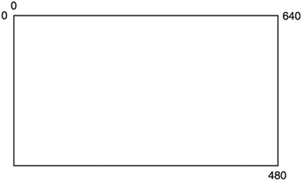
The area in which the sprites are drawn, in this case, will consist of the entire viewport. The SetProjectionTransform function is used to set the available drawing area for the sprite object. The SetProjectionTransform function takes one parameter, a D3DXMATRIX
structure called the projection matrix, which defines the dimensions of
the drawing area.
The function D3DXMatrixOrthoOffCenterLH is used to create the projection matrix. The first parameter for this function is a pointer to a D3DXMATRIX structure where the resulting projection matrix is placed. D3DXMatrixOrthoOffCenterLH
creates a left-handed projection matrix that is used for setting up the
viewport for sprite drawing. This function is used specifically to
offset the coordinates used causing the top-left corner to be at 0, 0.
The second, third, fourth, and fifth parameters define the drawing area.
The
last two parameters determine the depth of the scene. Even though
sprites have no depth, the projection matrix needs valid depth values.
The depth values are used by the system to figure out when to clip
pieces of the scene.
The following code sample shows how to create a projection matrix based on the viewport.
The projection matrix
D3DXMATRIX matProjection;

// Create the projection matrix using the values in the viewport
D3DXMatrixOrthoOffCenterLH(&matProjection,
    (float)viewPort.TopLeftX,
    (float)viewPort.Width,
    (float)viewPort.TopLeftY,
    (float)viewPort.Height,
    0.1f,
    10);

// Set the projection matrix
HRESULT hr = spriteObject->SetProjectionTransform(&matProjection);
The projection matrix lets
the system know the size of the grid on which the sprites will be
placed. In the previous code sample, if the viewport is 640 pixels wide
and 480 pixels tall, then the projection matrix would restrict visible
sprite drawing to that area. Sprites positioned outside of this area
would not be visible on the screen.
The projection matrix only needs to be changed if the size of the viewport changes.
Positioning and Scaling the Sprite
Now that the sprites know
the extent of their environment, positioning them within it is
possible. The act of moving an object within a space is called
translation. Sprites being two dimensional in nature can be translated
in two directions, X and Y. If you want to position a sprite in the
center of a 640 × 480 display area, you would translate the sprite to an
X, Y position of (320, 240). This in effect, moves the sprite 320
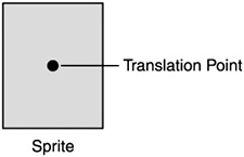
pixels horizontally and 240 pixels vertically. When sprites are
translated, they’re moved based on an internal point called the
translation point. The translation point on a sprite is by default in
the sprite’s center. You can see an example of a sprite’s translation
point in Figure 4.
Because the default
translation point for the sprite was in its center, the sprite appears
correctly centered on the screen. When using sprites for characters
within a game, it is common for the translation point to be moved to the
top-left corner of the sprite.
When translating a
sprite it is necessary to create another matrix called the translation
matrix. The translation matrix, once defined, is used by Direct3D to
position the sprite. The translation matrix can be created by using the
function D3DXMatrix Translation. The D3DXMatrixTranslation function uses four parameters.
The first parameter is a pointer to the output translation matrix.
The second and third parameters are the X and Y position where the sprite should be moved.
The final parameter is the depth at which the sprite should be placed.
The following code sample shows how to use this function.
// these variables describe the dimensions of the sprite
// and where it should be located.
float spritePosX = 320;
float spritePosY = 240;
float spriteWidth = 64;
float spriteHeight = 64;

// The translation matrix to be created
D3DXMATRIX matTranslation;

// Create the translation matrix
D3DXMatrixTranslation( &matTranslation,
    spritePosX,
    (windowHeight - spritePosY),
    0.1f);
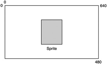
When positioning
a sprite vertically, it is necessary to subtract the destination Y
position from the height of the application window. This allows the
sprite to be positioned based on the top-left corner of the window. Figure 5 shows a diagram of a sprite centered in the viewport area.
By default, Direct3D
will draw your sprites only 1 pixel tall and 1 pixel wide. To make sure
your sprite gets drawn at its correct size, the sprite must be scaled.
Scaling the sprite requires the use of one more matrix, the scaling
matrix.
The scaling matrix is created using the D3DXMatrixScaling function.
The D3DXMatrixScaling function takes four parameters.
The first parameter
is a pointer to the output scaling matrix. The second and third
parameters are the values by which to scale the sprite in the X and Y
directions, respectively. Passing in the sprite’s width and height
values will make sure the sprite is sized correctly.
The final parameter is
the amount to scale the sprite’s depth. Since the sprite shouldn’t be
scaled in this direction, you should pass 1.0f as the default value.
The following code sample shows how to use the D3DXMatrixScaling function to create the scaling matrix.
// Scale the sprite to its correct width and height
D3DXMATRIX matScaling;
D3DXMatrixScaling(&matScaling, spriteWidth, spriteHeight, 1.0f );
So now that you have the translation matrix and the scaling matrix, what do you do with them? Do you remember the matWorld parameter of the D3DX10_SPRITE
structure? This parameter is the world transform, which positions the
sprite. The translation and scaling matrices need to be multiplied
together to get the correct value for the matWorld parameter. This code snippet shows how this is accomplished.
// The sprite structure, the rest of the parameters should be filled in as well.
D3DX10_SPRITE testSprite;

// Setting the sprite's position and size
testSprite.matWorld = (matScaling * matTranslation);
You’ve come a long way so far; there’s only one more step, drawing.
Drawing the Sprite
The drawing of a sprite takes place within your render function. Previously, you had used the Render function to clear the render target. Now, you’re going to add the drawing of the sprite as well.
To draw the sprite, you need some functionality provided by the sprite object (ID3DX10Sprite). All drawing of sprites takes place between two calls, Begin and End. Seems simple enough. The Begin call prepares Direct3D to draw sprites, setting up the proper internal states. The End call finalizes the drawing. Table 1 shows the possible flags that can be sent to the Begin function.
Table 1. Sprite Flags
| Flag | Description |
|---|
| D3DX10_SPRITE_SORT_TEXTURE | Sort the sprites by texture. |
| D3DX10_SPRITE_SORT_DEPTH_BACK_TO_FRONT | Sort the sprites from back to front based on Z order. |
| D3DX10_SPRITE_SORT_DEPTH_FRONT_TO_BACK | Sort the sprites from front to back based on Z order. |
| D3DX10_SPRITE_SAVE_STATE | Makes sure the render state before sprite drawing is restored when the End function is called. |
| D3DX10_SPRITE_ADDREF_TEXTURES | Causes the reference count for each sprite texture to be incremented. |
Tip
Sprites
can be made to have transparent areas by giving their textures an alpha
layer in your paint program and applying a Direct3D blend state.
The key function for sprite drawing is the DrawSpritesImmediate function. This is the function that takes the sprite and sends it to the video card to be drawn. The DrawSpritesImmediate function takes four parameters.
The first parameter is the sprite structure you created earlier, testSprite.
The second parameter is the number of sprites that DrawSpritesImmediate is expected to draw. In this example, only one sprite is needed.
The third parameter is the size of the D3DX10_SPRITE structure. Passing 0 will default to the proper size.
The final parameter is reserved and should be set to 0.
The DrawSpriteImmediate function has the capability of drawing more than one sprite. This functionality will be explained in the next section.
/*******************************************************************
* Render
* All drawing happens in the Render function
* Inputs - void
* Outputs - void
*******************************************************************/

void Render()
{
    if (pD3DDevice != NULL)
    {
        // clear the target buffer
        pD3DDevice->ClearRenderTargetView(pRenderTargetView, D3DXCOLOR (0.0f,
        0.0f, 0.0f, 0.0f));

        // start drawing the sprites
        spriteObject->Begin(D3DX10_SPRITE_SORT_TEXTURE);

        // Draw all the sprites
        spriteObject->DrawSpritesImmediate(testSprite, 1, 0, 0);

        // Finish up and send the sprites to the hardware
        spriteObject->End();

        // display the next item in the swap chain
        pSwapChain->Present(0, 0);
    }
}